T1 ToneMatch® Audio Engine to F1 System
| This article describes how to connect a T1 ToneMatch Audio Engine to an F1 Model 812 Flexible Array Loudspeaker. If the T1® is not connected to a L1 Model II or L1 Model 1S then you will need a T1_ToneMatch%C2%AE_Audio_Engine_power_supply.
Please post comments or questions in this discussion in the Bose Forum. Thank you.
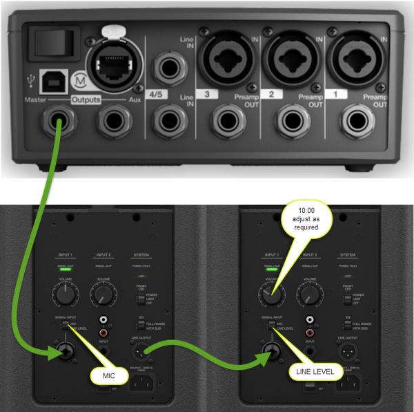
Connecting the T1® to the F1 Model 812 Channel 1, you can set the Signal Input switch to MIC instead of Line Level if you need more volume from the F1. You will not harm the system by doing this. You can also turn up the F1 Channel 1 Volume until you are seeing long red flickers (up to 1 second). If you are seeing solid red, then turn the Volume control down.
For best results use a ¼ inch jack Tip-Ring-Sleeve cable from the T1® to the F1 Model 812. |
Mono Connection
This describes how you can run an L1 Model II or L1 Model 1S with a T1 ToneMatch Audio Engine and run one or more F1 Model 812 Flexible Array Loudspeakers at the same time.
To connect a T1 ToneMatch Audio Engine to an F1 Model 812 Flexible Array Loudspeaker you will run a cable from the T1® Master Output to the F1 Model 812 Flexible Array Loudspeaker Channel 1 or Channel 2 1/4 input.
You can connect a second F1 Model 812 with an XLR cable from the first F1 Model 812 Line Out to Channel 1 on the second F18.
For best results use a balanced connections
- ¼ Inch Tip-Ring-Sleeve (balanced) to ¼ Inch Tip-Ring-Sleeve (balanced)
A balanced connection is preferred and will provide better noise rejection over greater distances than the unbalanced connection.
The output from the T1® is balanced mono, as are the XLR and ¼ inch inputs on the F1 System. Use a ¼ inch jack Tip-Ring-Sleeve cable to make a balanced connection. If you use a ¼ inch jack Tip-Sleeve cable you will be making an unbalanced connection (-6dB less gain than a balanced connection).
XLR connection from F1 Model 812 Line Out to second F1 Channel 1
Use an ordinary microphone cable to connect the first F1 Model 812 to the second one.
Using an F1 Subwoofer
Run the F1 Model 812 Line Out to the F1 Subwoofer Channel 1 Input.
Stereo Connection
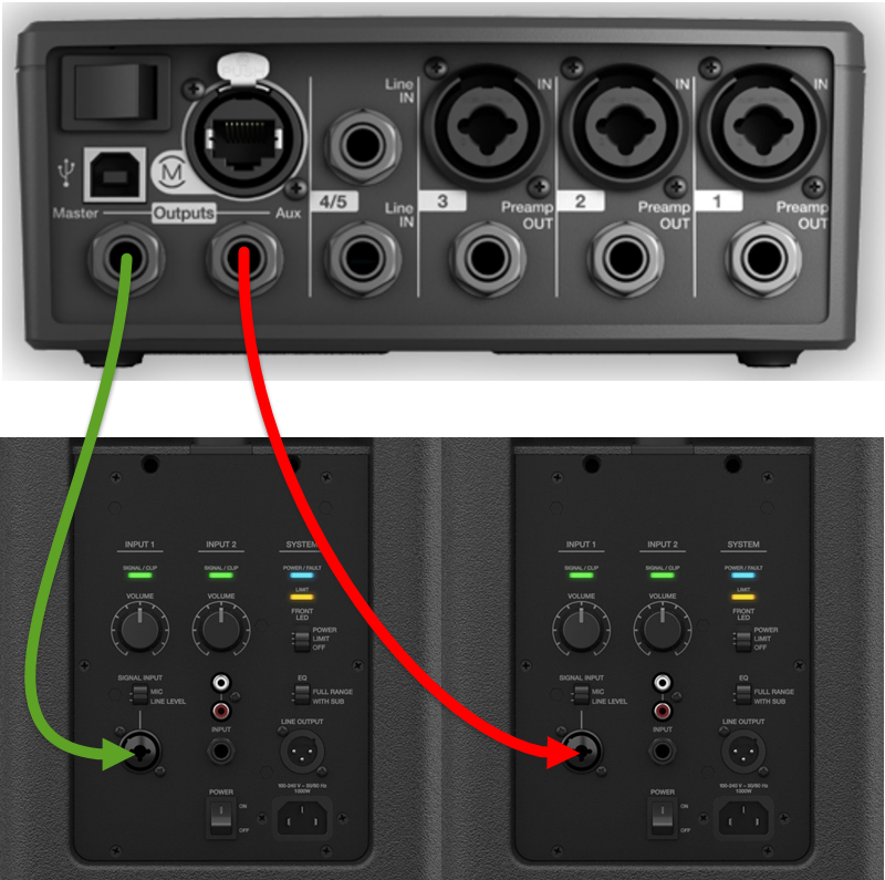
If you have split a stereo signal to T1® Master and T1® Aux see a detailed article T1 ToneMatch® Audio Engine / Stereo Output to Two F1 Systems.
Here is a quick overview.
For best results use a balanced connections
- ¼ Inch Tip-Ring-Sleeve (balanced) to ¼ Inch Tip-Ring-Sleeve (balanced)
A balanced connection is preferred and will provide better noise rejection over greater distances than the unbalanced connection.
The output from the T1® is balanced mono, as are the XLR and ¼ inch inputs on the F1 System. Use a ¼ inch jack Tip-Ring-Sleeve cable to make a balanced connection. If you use a ¼ inch jack Tip-Sleeve cable you will be making an unbalanced connection (-6dB less gain than a balanced connection).
XLR connection from F1 Model 812 Line Out to second F1 Channel 1
Use an ordinary microphone cable to connect the first F1 Model 812 to the second one.
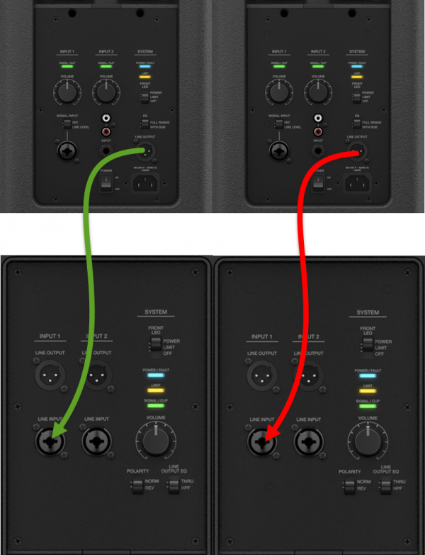
Using F1 Subwoofers
Run the F1 Model 812 Line Out to the F1 Subwoofer Channel 1 Input.


